Choosing a panel mount touch screen monitor sounds straightforward until the sample arrives and doesn't fit your enclosure. I've seen it happen repeatedly: a buyer selects a display based on screen size and brightness, only to discover the mounting depth exceeds available clearance or the bezel doesn't match the panel cutout.
A panel mount touch screen monitor should be chosen by first confirming physical fit—panel cutout dimensions, mounting depth, and rear clearance—then assessing real-world readability in your specific lighting and viewing conditions, and finally matching touch technology, interfaces, and power requirements to your system design.
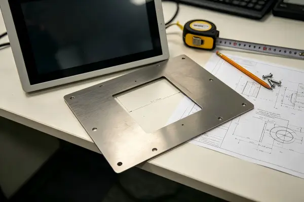
The selection process is not about picking specifications from a datasheet. It is an integration decision. Below, I'll walk through the structured approach we recommend to our customers to avoid costly rework.
Why should you start with the installation envelope instead of screen size?
Most buyers begin their search by specifying a diagonal size—10.1", 15.6", 21.5". But two monitors with the same active area can have completely different overall dimensions, cutout requirements, and mounting depths[1].
The installation envelope—the physical space your equipment allocates for the monitor—is the true starting constraint. If you don't confirm fit first, everything else becomes irrelevant.
What dimensions actually matter?
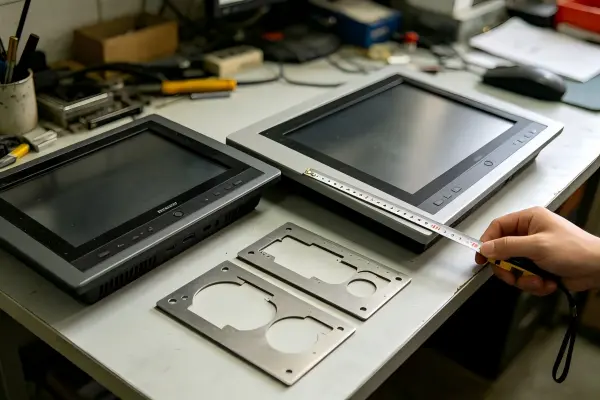
When evaluating a panel mount touch screen monitor for physical fit, you need to distinguish several measurements:
| Dimension | What It Means | Why It Matters |
|---|---|---|
| Active area | The visible display surface | Determines usable screen real estate |
| Overall enclosure size | Outer dimensions of the monitor housing | Must not exceed your panel opening or available front space |
| Panel cutout | The rectangular hole in your equipment panel | Must match the monitor's specified cutout exactly |
| Bezel overlap | How much the front bezel extends beyond the cutout | Affects aesthetic flush mounting and sealing |
| Mounting depth | How far the monitor protrudes behind the panel | Must fit within your enclosure's internal clearance |
| Rear clearance | Space needed behind the monitor for cables, airflow, connectors | Often overlooked until installation |
A real pattern we see repeatedly
In pre-sales conversations, buyers frequently provide a screen diagonal and ask for a quote. When we send back the mechanical drawing, they realize their panel cutout was designed for a different vendor's unit—off by 5–10 mm in one direction[2]. That gap means either re-cutting the panel or finding a different monitor.
My recommendation: Request the mechanical drawing before anything else. Compare it against your panel design with your mechanical engineer. Confirm not just width and height, but depth and connector orientation.
How do you cross-check physical fit before purchasing?
Even experienced equipment manufacturers occasionally skip a step in the fit verification process. The result is delayed projects and wasted samples.
Turn your question from "Will this fit?" into a structured cross-check. Compare the monitor's dimensional drawing against your equipment panel, internal space, cable routing paths, connector positions, and future service access requirements.
A practical pre-purchase checklist
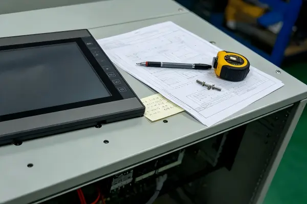
Before sampling or ordering a panel mount touch screen monitor, verify:
- Panel cutout matches the monitor's specification — tolerance matters; confirm ±mm allowance
- Mounting depth fits within internal clearance — account for brackets, clips, or studs
- Rear cable connectors have routing space — right-angle vs. straight connectors change depth needs[3]
- Mounting method is compatible — rear studs, clamps, VESA, or custom brackets
- Service access remains possible — can you remove the monitor without disassembling the entire enclosure?
Fixing method variations
Not all panel mount monitors use the same fixing approach. Some use threaded rear studs with nuts tightened from behind. Others use spring clips or side clamps. Your panel thickness and material affect which methods work. A 2 mm steel panel handles threaded studs well; a thin aluminum composite panel may not[4].
Key takeaway: Never assume two monitors with the same screen size are interchangeable. The mounting interface defines compatibility.
Does higher brightness always mean better readability?
This is one of the most common misconceptions. Buyers often request "1000 nits" or "high brightness" as a blanket requirement, assuming it guarantees readability. Brightness is one input to readability—not the whole story.
A panel mount touch screen monitor's readability depends on ambient light intensity, light direction, surface reflections, viewing angle, viewing distance, and what information users must actually read on screen.

Factors beyond brightness
- Glare and reflections: A glossy touch surface in direct sunlight can wash out a 1000-nit display[5]. Anti-glare treatments[6] or optical bonding[7] may matter more than raw brightness.
- Viewing angle: If operators view the screen from an oblique angle, contrast drops. IPS panels maintain readability across wider angles than TN panels[8].
- Installation angle: A vertically mounted screen facing a window receives different light than a tilted screen under overhead fluorescents.
- Content type: Small text requires higher contrast ratios than large icons or color-coded status indicators[9].
What should you do instead?
- Document where the monitor will be installed—indoors, semi-outdoor, or outdoor
- Identify the primary light sources and their direction relative to the screen
- Determine the typical viewing distance and angle
- Discuss these conditions with your supplier to select appropriate brightness, surface treatment, and panel technology
Do not equate a brightness specification with guaranteed outdoor readability. On-site validation remains the buyer's responsibility.
What selection sequence avoids integration rework?
Approaching panel mount touch screen monitor selection as a project-based sequence—rather than a feature shopping list—prevents the most common rework scenarios.
Define mounting structure and installation constraints first, assess the viewing environment second, then confirm touch technology, signal interfaces, power supply, and any customization needs with your relevant teams.

Recommended sequence
| Step | Focus Area | Who Should Be Involved |
|---|---|---|
| 1 | Mounting dimensions and physical fit | Mechanical/structural engineer |
| 2 | Viewing environment and readability | Site/installation team |
| 3 | Touch technology (resistive, capacitive, etc.) | End-user workflow designer |
| 4 | Signal interface (HDMI, VGA, DVI, etc.) | System/electrical engineer |
| 5 | Power requirements and thermal conditions | Electrical engineer |
| 6 | Customization (branding, bezels, special coatings) | Project manager |
Why this order works
Physical fit is binary—it either fits or it doesn't[10]. Starting here eliminates options that can never work, regardless of their other features. Readability assessment follows because it's environment-dependent and may require trade-offs (brightness vs. cost, surface treatment vs. touch sensitivity). Touch and interface selections come last because they're typically more flexible and available across multiple form factors.
Frequently Asked Questions
Can I use the same panel cutout for monitors from different suppliers?
Not reliably. Even monitors with identical screen diagonals often differ in cutout dimensions by several millimeters. Always compare the mechanical drawing from each supplier against your panel design before ordering.
Is capacitive touch always better than resistive for panel mount monitors?
Not universally. Capacitive touch offers better clarity and multi-touch[11], but resistive touch works with gloves and styluses[12]. Your choice depends on the operator's working conditions and interaction requirements.
How do I know if my enclosure has enough depth for a panel mount monitor?
Check the monitor's mounting depth specification on its mechanical drawing, then add clearance for connectors and cable bends. Measure the available space behind your panel to the nearest internal obstruction.
Should I request a sample before committing to a batch order?
Yes, whenever possible. A physical sample lets you verify dimensional fit, assess display quality in your actual lighting, and confirm connector accessibility—things no datasheet can fully guarantee.
Conclusion
Choosing a panel mount touch screen monitor is an integration decision, not a catalog exercise. Start with physical fit—confirm cutout dimensions, mounting depth, and rear clearance against your mechanical drawings. Then assess readability in your actual viewing environment rather than relying on brightness numbers alone. Finally, align touch, interface, and power requirements with your system teams.
At AplusLCD, we provide detailed mechanical drawings and engineering support early in the selection process specifically to help buyers avoid integration surprises. If you're specifying a panel mount touch screen monitor for your next project, share your panel drawings and installation conditions with our team—we'll help you cross-check fit and readability before you commit.
Related Reading
Footnotes
-
"VESA mount", https://en.wikipedia.org/wiki/VESA_mount. Industry mounting standards such as those defined by VESA specify active area and mounting hole patterns but do not constrain overall enclosure dimensions, meaning manufacturers of same-diagonal displays may produce housings that differ by 10 mm or more in width and height. Evidence role: general_support; source type: institution. Supports: That industrial display monitors of the same nominal screen diagonal can differ substantially in overall housing dimensions and mounting cutout requirements due to bezel width, housing design, and mounting hardware variations. Scope note: Standards documents define interface specifications rather than directly measuring variation across commercial products ↩
-
"Industrial Panel Mount Display - Strongarm Designs", https://strongarm.com/strongarm-products/industrial-panel-mount-display/. Unlike traditional panel instruments governed by DIN 43700 which defines standard cutout sizes (e.g., 92×92 mm, 138×138 mm), industrial panel mount monitors lack a universal cutout standard, with manufacturers independently determining housing dimensions based on their own bezel and mounting designs. Evidence role: general_support; source type: institution. Supports: That panel cutout dimensions for industrial displays are not universally standardized across manufacturers, leading to dimensional incompatibilities when substituting between vendors. Scope note: The DIN 43700 standard applies to traditional instruments rather than monitors specifically, and the 5-10 mm variation claim remains anecdotal ↩
-
"1926.403 - General requirements. | Occupational Safety ...", http://www.osha.gov/laws-regs/regulations/standardnumber/1926/1926.403. Standard HDMI connectors with straight cable exit require approximately 40–55 mm of clearance behind the receptacle (including cable bend radius), while right-angle adapters or side-exit connectors can reduce this to 15–25 mm, a critical consideration in depth-constrained panel mount installations. Evidence role: general_support; source type: other. Supports: That straight-exit cable connectors add significant depth behind a panel mount device compared to right-angle alternatives, often requiring 30-50 mm additional clearance depending on connector type. Scope note: Exact clearance requirements vary by connector type (HDMI, VGA, USB, power) and cable gauge ↩
-
"Electrical Enclosure Materials", https://www.nemaenclosures.com/materials/?srsltid=AfmBOoqGhF6Ufb6OP3Ufjb2HH0UrO2uLSfppNDxkZg2hoDhWl3lVfGXL. Industrial enclosure standards such as IEC 61439 specify minimum panel thicknesses for equipment mounting, with steel panels typically requiring 1.5–2 mm minimum thickness for secure fastener retention, while composite or thin-gauge aluminum panels may require reinforcement plates to distribute mounting loads without deformation. Evidence role: general_support; source type: institution. Supports: That the mechanical integrity of threaded stud mounting depends on panel material properties and thickness, with minimum thickness requirements varying by material type. Scope note: Specific load-bearing capacity depends on stud spacing, monitor weight, and vibration environment rather than panel material alone ↩
-
"Lighting and Reflections - Video Displays, Work, and Vision", https://www.ncbi.nlm.nih.gov/books/NBK216496/. Military standard MIL-STD-3009 establishes that display readability under sunlight (approximately 100,000 lux) requires not only high luminance output but also low surface reflectance, as specular reflections from untreated glass surfaces can produce luminance values exceeding the display's own output, reducing effective contrast ratio below legibility thresholds. Evidence role: mechanism; source type: government. Supports: That display readability in high ambient light depends on the ratio of emitted luminance to reflected ambient luminance, and that specular reflections from glossy surfaces can exceed display output even at 1000 cd/m². Scope note: Military standards address specific use cases and may not directly map to all industrial panel mount applications ↩
-
"A novel method to control inner and outer haze of an anti- ...", https://www.sciencedirect.com/science/article/abs/pii/S0021979710007861. Anti-glare (AG) treatments apply a micro-roughened texture to the display surface that diffuses specular reflections into a broader angular distribution, reducing perceived glare intensity; however, this scattering introduces haze (typically 5–40%) which can reduce perceived sharpness and contrast compared to optically clear surfaces. Evidence role: mechanism; source type: research. Supports: That anti-glare surface treatments use micro-textured surfaces to scatter specular reflections, reducing mirror-like glare at the cost of some image sharpness. Scope note: The optimal haze level and treatment type depend on specific ambient lighting conditions and display application ↩
-
"In-Depth Analysis of Optical Bonding Technology", https://goldenmargins.com/in-depth-analysis-of-optical-bonding-technology/. Optical bonding fills the air gap between cover glass and display with an optically clear adhesive, eliminating two glass-air interfaces that each reflect approximately 4% of incident light per Fresnel equations, thereby reducing total internal reflections and improving sunlight-readable contrast by up to 400%. Evidence role: mechanism; source type: research. Supports: That optical bonding eliminates the air gap between the touch panel and LCD, reducing internal reflections and improving contrast ratio in high ambient light conditions. Scope note: Improvement percentages vary depending on specific materials, coatings, and ambient light conditions ↩
-
"In-plane switching", https://en.wikipedia.org/wiki/In-plane_switching. IPS panels typically maintain usable contrast ratios at viewing angles up to 178° both horizontally and vertically, whereas TN panels exhibit significant contrast and color shift beyond approximately 45° from perpendicular, due to the different liquid crystal alignment mechanisms employed by each technology. Evidence role: mechanism; source type: encyclopedia. Supports: That IPS (In-Plane Switching) LCD panels maintain higher contrast ratios and more accurate color reproduction at oblique viewing angles compared to TN (Twisted Nematic) panels. Scope note: Specific viewing angle performance varies by manufacturer implementation and generation of panel technology ↩
-
"Accessibility Bytes No. 2: Color Contrast", https://www.section508.gov/blog/accessibility-bytes/color-contrast/. ISO 9241-303 (Ergonomics of human-system interaction — Electronic visual displays) establishes that character legibility depends on the interaction of contrast ratio, character height, and viewing distance, with smaller characters requiring proportionally higher contrast ratios to achieve equivalent readability performance. Evidence role: expert_consensus; source type: institution. Supports: That smaller displayed characters require higher contrast ratios to maintain legibility, as established by display ergonomics standards. Scope note: The standard provides guidelines for office environments and may not directly specify thresholds for all industrial viewing conditions ↩
-
"Constraint based Modeling according to Reference Design", https://arxiv.org/html/2407.00064v1. Systems engineering methodologies such as Pugh's controlled convergence and constraint-satisfaction approaches recommend screening candidate solutions against non-negotiable physical constraints before evaluating performance trade-offs, as this eliminates infeasible options early and reduces the decision space for subsequent optimization. Evidence role: general_support; source type: education. Supports: That engineering design selection methodologies recommend evaluating hard constraints (binary pass/fail criteria) before optimizing soft constraints (continuous trade-off parameters). Scope note: General systems engineering principles are applied here by analogy to component selection rather than being specific to display procurement ↩
-
"Review of Capacitive Touchscreen Technologies - PMC - NIH", https://pmc.ncbi.nlm.nih.gov/articles/PMC8309784/. Projected capacitive (PCAP) touch sensors typically achieve 90–92% optical transmittance using a single glass substrate with transparent ITO electrode patterns, compared to 75–82% for resistive panels which require two ITO-coated substrates separated by an air gap, with each additional interface introducing reflection and absorption losses. Evidence role: mechanism; source type: research. Supports: That projected capacitive touch panels achieve higher optical transmittance than resistive panels due to fewer layers and the elimination of the flexible top membrane. Scope note: Transmittance values vary by manufacturer, electrode pattern density, and whether cover glass is included in the measurement ↩
-
"Touchscreen", https://en.wikipedia.org/wiki/Touchscreen. Resistive touch panels operate via pressure-induced contact between two transparent conductive layers (typically ITO-coated PET and glass), registering input from any object that applies sufficient force, whereas projected capacitive touch panels detect changes in electrical capacitance and require a conductive object such as a bare finger or specialized capacitive stylus. Evidence role: mechanism; source type: encyclopedia. Supports: That resistive touch screens detect input through physical pressure causing two conductive layers to make contact, enabling operation with any object including gloved fingers and styluses, unlike projected capacitive screens which require a conductive input. Scope note: Modern projected capacitive panels can be tuned for glove sensitivity, partially narrowing this distinction ↩