Touch drift and malfunctions on open frame monitors can delay AI hardware deployments and lead teams to replace parts too early. When a touch screen works on the bench but fails after integration, we need to separate the visible symptom from the actual system condition before we blame the monitor.
Touch drift and malfunctions on open frame monitors for high-speed AI hardware should be diagnosed by isolating the symptom, checking touch-controller and USB compatibility, and comparing operation before and after system integration. Recalibration may help coordinate offset in some cases, but ghost touches, intermittent failures, and total touch loss require different checks. We recommend verifying enclosure, grounding, cable routing, and connected equipment in the real deployment environment before replacing the display.
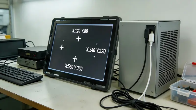
In our customer conversations at AplusLCD, we often hear that touch problems appear only after final assembly. That timing matters. We use a practical, step-by-step process to help project teams collect useful evidence before they escalate a case or change hardware.
For the standard open frame range these teams integrate — LH and LD series sizes, brightness, touch and mounting — see our Open Frame Monitor Guide.
How Do We Identify the Type of Touch Drift and Malfunction?
A vague report such as “the touch screen is unstable” creates a difficult troubleshooting path. If we treat every fault as touch drift, we may recalibrate a screen that actually has an intermittent USB connection or a system-level integration issue.
We identify touch drift and malfunctions on open frame monitors by classifying the symptom first: coordinate offset, ghost touches, intermittent touch response, or complete touch loss[1]. Each symptom suggests a different diagnostic path, so teams should record what the screen does, when it starts, and whether a reconnection changes it.
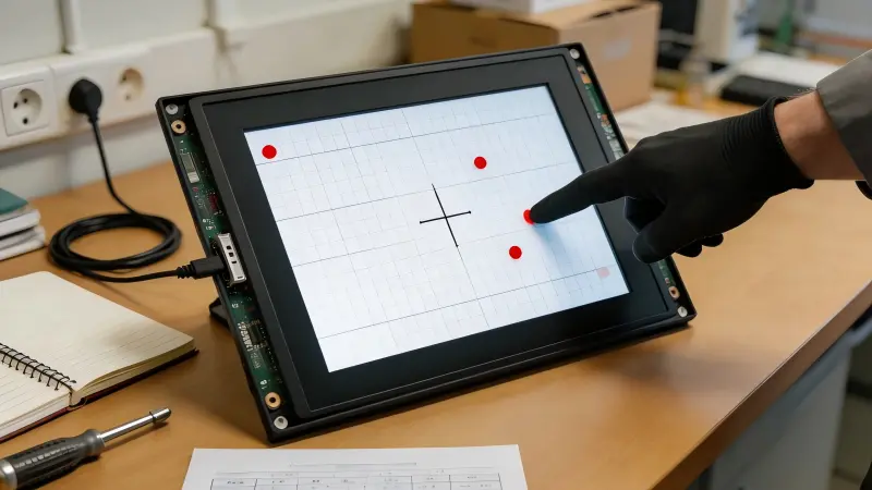
Separate the symptom from the suspected cause
We recommend that teams avoid starting with assumptions such as “the GPU is causing interference” or “the touch panel is defective.” High-speed AI hardware, GPU workstations, power systems, metal structures, and USB peripherals can all be variables in an installation. They are not automatic root causes.
In our project follow-ups, we have seen several recurring symptom patterns:
| Symptom | What the operator sees | Useful first checks |
|---|---|---|
| Coordinate offset | Touch registers away from the finger position | Orientation, controller settings, calibration, display mapping |
| Ghost or random touches | Inputs occur without contact | Cable condition, controller behavior, grounding and installation changes |
| Intermittent touch | Touch works, then stops or drops out | USB connector fit, cable routing, power-up sequence, host compatibility |
| Total touch loss | No touch input reaches the host | USB detection, controller power, interface selection, operating-system recognition |
A coordinate offset can sometimes be related to display rotation, incorrect mapping between multiple displays, or a calibration setting.[2] In contrast, random touches should not be treated as a simple calibration issue. Likewise, a monitor with no touch response may still have a working LCD image, because the display video signal and touch-control signal are usually separate paths[3].
We ask customers to record a short video when possible. A video can show whether the cursor shifts consistently, jumps randomly, disappears after a delay, or returns after reconnection.
This evidence helps our team and the customer’s engineering team use the same language. It also reduces unnecessary return shipments and component replacement.
Can USB Configuration and Touch-Controller Compatibility Cause Touch Drift?
When touch behavior changes after a system is connected, teams may focus only on the monitor. However, the USB touch connection, host operating system, controller configuration, and cable assembly deserve equal attention.
USB configuration and controller compatibility can contribute to touch drift and malfunctions on open frame monitors when the host does not recognize the device consistently, the touch mapping is incorrect, or the connection changes after installation. We recommend confirming the touch technology, controller interface, USB detection status, and display arrangement before replacing hardware.
Verify the basic touch chain
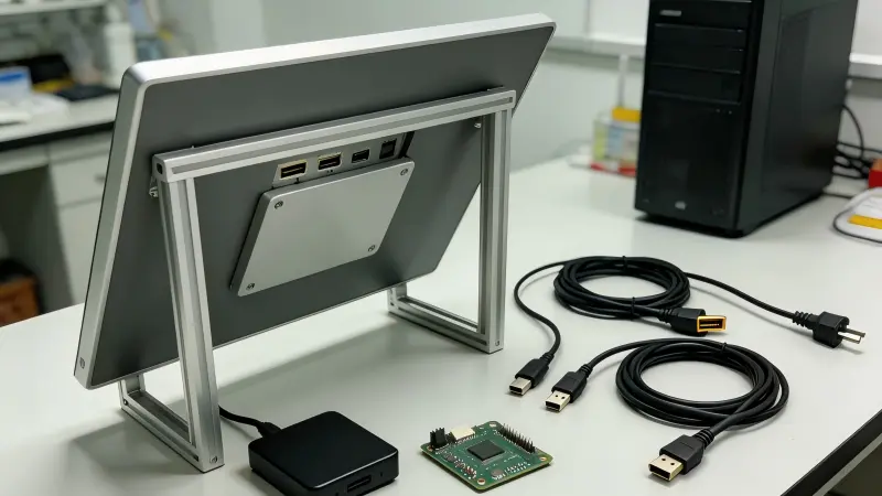
Most industrial touch-monitor projects involve at least two signal paths:
- Video input, such as HDMI, DisplayPort, VGA, or another specified interface.
- Touch-control input, commonly USB, which sends touch data to the host system.
A clear image does not prove that the touch connection is healthy. We recommend checking whether the operating system detects the USB touch device[4], whether it reconnects unexpectedly, and whether the problem changes when the cable is disconnected and reconnected.
In our experience, a simple reconnection test can provide useful diagnostic information. It does not prove the cause, but it can show that the symptom is connection-sensitive. For example, if touch returns after reconnecting USB but fails again after the enclosure is closed, the integration condition deserves closer review — a repeatable pattern like that points to the connection chain and installation rather than to the monitor itself.
Use recalibration as a conditional test
We do not present recalibration as either useless or universal. It is most relevant when:
- The touch point is consistently offset.
- The monitor orientation has changed.
- The host uses multiple displays.[5]
- The display resolution or scaling configuration has changed.
- The operating system supports a calibration or touch-mapping process.
Recalibration is less likely to address random inputs, USB dropouts, or complete loss of touch. In those cases, teams should document the controller model, operating system version, interface type, cable length, and connection sequence.
For procurement teams, this is also a supplier-selection issue. Buyers should confirm the intended touch technology, USB interface, driver expectations, operating-system compatibility, and long-term controller availability before approving a display design. At AplusLCD, we encourage customers to define these requirements during pre-sales review rather than after final mechanical assembly.
How Should We Test Metal Enclosures and Nearby AI Hardware?
A touch fault that appears after metal-enclosure installation can be frustrating. The temptation is to label the enclosure or nearby GPU equipment as the cause. We recommend a more disciplined approach because the actual deployment conditions can involve several simultaneous changes.
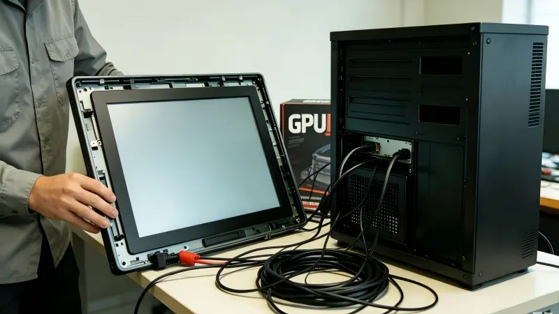
We test touch drift and malfunctions on open frame monitors near AI hardware by changing one condition at a time[6]: monitor mounting, USB routing, enclosure state, host connection, and nearby equipment status. This isolation process helps teams identify correlations without treating metal enclosures or high-power hardware as proven universal causes.
Build a practical comparison sequence
We suggest recording results in a simple installation log. The goal is not to create laboratory evidence. The goal is to make the field condition repeatable enough for engineering review.
| Test condition | What to record |
|---|---|
| Monitor on a bench | Touch accuracy, USB detection, host system used |
| Monitor mounted without final enclosure closure | Changes in touch response or stability |
| Enclosure fully assembled | Exact point when the symptom appears |
| USB cable rerouted or replaced with a known-good test cable | Whether the symptom changes |
| AI/GPU equipment connected or powered in normal sequence | Timing of any change, not assumed causation |
We have received customer reports where touch behavior changed after the monitor was installed into a metal structure. We treat these reports as useful clues, not proof that the enclosure damaged the touch screen. The installation may also change cable bends, connector strain, mounting pressure, grounding arrangements, power-up order, or distance from other system components.[7]
Review integration details carefully
For open frame monitors, mechanical integration matters. A panel can be mounted in a way that creates pressure near an active area or controller connection. A USB cable can be routed tightly around other components. A connector can appear seated but become stressed after a kiosk door closes or a panel PC is installed.
We recommend that project teams verify:
- The monitor is mounted according to the approved mechanical design.
- No bezel, bracket, or enclosure part applies unintended pressure.
- USB and video cables are securely connected and not sharply bent.
- Cable routing is documented before and after final assembly.
- Grounding and power arrangements are reviewed by qualified personnel.[8]
- The same monitor is tested with the same host both inside and outside the final installation.
For application-specific decisions involving high-power AI hardware, electrical systems, or regulated equipment, we recommend evaluation by qualified engineering professionals. Buyers should also verify relevant supplier documents, interface specifications, and any claimed certifications for their own product and market requirements.
Frequently Asked Questions
Can recalibration fix touch drift on an open frame monitor?
Recalibration can help when touch coordinates are consistently offset because of orientation, display mapping, scaling, or supported controller settings. It is less likely to solve ghost touches, intermittent USB disconnection, or total touch loss. We recommend classifying the symptom before recalibrating.
Does a metal enclosure cause touch screen failure?
A metal enclosure does not automatically cause touch screen failure. If a fault appears after installation, we recommend checking mounting pressure, cable routing, USB connections, grounding arrangements, and changes introduced during assembly. Isolation testing provides stronger evidence than assumptions.
Can AI GPUs cause random touch inputs?
We cannot treat AI GPUs or high-power hardware as proven universal causes of random touch inputs. Nearby equipment may be one site-specific variable to test, but teams should also inspect controller configuration, USB behavior, enclosure integration, and mechanical installation conditions.
Should we replace the touch monitor if USB reconnection restores touch?
Not immediately. If USB reconnection changes the symptom, we consider that a useful clue about the connection chain or system state. We recommend documenting the result, testing a known-good connection path, and comparing bench operation with the final installed system.
Conclusion
Touch drift and malfunctions on open frame monitors require structured diagnosis rather than quick assumptions. We recommend that teams classify the symptom, check touch-controller and USB compatibility, use recalibration only when appropriate, and compare behavior before and after integration. Metal enclosures and high-speed AI hardware should be verified as site-specific variables through controlled changes. If your project needs an industrial open frame touch monitor with defined interfaces, mounting options, and customization support, we invite you to contact AplusLCD for a practical pre-sales review.
Related Reading
Footnotes
-
"Windows Touchscreen calibration not working?", https://learn.microsoft.com/en-us/answers/questions/2318026/windows-touchscreen-calibration-not-working. Technical touchscreen documentation distinguishes positional inaccuracy, unintended touch events, intermittent device behavior, and unavailable touch input as different observable failure modes that warrant separate troubleshooting. Evidence role: definition; source type: research. Supports: Definitions of common touchscreen failure manifestations, including positional offset, unintended contacts, intermittent input, and loss of input.. Scope note: Terminology and diagnostic categories may differ by touch technology, controller, and operating system. ↩
-
"Problem calibrating touchscreen on Windows 7", https://learn.microsoft.com/en-us/answers/questions/2445727/problem-calibrating-touchscreen-on-windows-7. Platform documentation on touch calibration and display assignment shows that touch coordinates may require configuration when display orientation, scaling, or the association between touch devices and multiple displays changes. Evidence role: mechanism; source type: government. Supports: Operating-system touch calibration and display-mapping settings can affect the correspondence between a physical touch position and the displayed coordinate.. Scope note: This support concerns host configuration and does not establish that every coordinate offset is caused by calibration or display mapping. ↩
-
"Simple touch screen type 1", https://www.lib.pacificu.edu/cetci/podium-setup-instructions/simple-touch-screen-1/. External touch displays commonly use a video interface for image transport and a separate USB Human Interface Device connection for touch reporting; therefore, normal video output alone does not establish that the touch-data path is operational. Evidence role: mechanism; source type: institution. Supports: Many external touch displays carry video through a video interface while reporting touch input through USB or another dedicated input interface.. Scope note: Some integrated products use different architectures or combined interfaces, so the signal arrangement should be verified for the specific monitor. ↩
-
"hid compliant touch screen driver - Microsoft Q&A", https://learn.microsoft.com/en-us/answers/questions/5830290/hid-compliant-touch-screen-driver. USB and HID documentation explains that a host must detect and enumerate a connected Human Interface Device before receiving its input reports, making device-recognition status relevant when USB touch input is unavailable. Evidence role: mechanism; source type: institution. Supports: USB Human Interface Devices must enumerate and be recognized by the host before their input reports can be used by the operating system.. Scope note: Successful enumeration does not by itself prove that touch mapping, controller firmware, or physical sensing is functioning correctly. ↩
-
"[SOLVED] Working touch-screen as secondary monitors on ...", https://learn.microsoft.com/en-us/answers/questions/3830521/solved-working-touch-screen-as-secondary-monitors. Operating-system guidance for pen and touch setup documents the need to identify or associate a touch-capable display in multi-monitor configurations, supporting verification of display mapping when touch is offset or directed to the wrong screen. Evidence role: general_support; source type: government. Supports: Multi-monitor systems may require touch input to be associated with the intended display.. Scope note: The exact setup procedure and available controls vary among operating systems and display-driver environments. ↩
-
"5.5.2.1. D-Optimal designs - Information Technology Laboratory", https://www.itl.nist.gov/div898/handbook/pri/section5/pri521.htm. Experimental-design guidance supports controlled comparison of conditions to evaluate whether an observed outcome changes with a specified factor; documenting one deliberate change at a time can improve traceability during field fault isolation. Evidence role: mechanism; source type: government. Supports: Controlled comparison of test conditions helps identify associations between a changed factor and an observed outcome.. Scope note: Single-factor testing can miss interactions among variables and establishes association rather than definitive causation without further validation. ↩
-
"Integration and Test Practices to Eliminate Stresses ...", https://llis.nasa.gov/lesson/729. Engineering reliability and electromagnetic-compatibility guidance identifies cable routing, connector stress, grounding practice, mechanical loading, and system configuration as installation variables that can affect electronic equipment behavior and should be controlled during troubleshooting. Evidence role: general_support; source type: government. Supports: Electronic-system installation can change cable integrity, connector loading, electromagnetic compatibility conditions, grounding, and mechanical loading, all of which are relevant engineering variables.. Scope note: The guidance supports reviewing these variables generally and does not prove that any particular installation variable caused a specific touch fault. ↩
-
"1910.333 - Selection and use of work practices.", http://www.osha.gov/laws-regs/regulations/standardnumber/1910/1910.333. Electrical-safety guidance defines qualified persons as individuals with appropriate training and demonstrated knowledge for electrical work, supporting review of grounding and power arrangements by personnel competent to assess the applicable installation hazards and requirements. Evidence role: expert_consensus; source type: government. Supports: Electrical safety frameworks define qualified persons and require competence for work involving electrical equipment and associated grounding arrangements.. Scope note: Specific legal duties, training criteria, and standards applicability depend on jurisdiction, voltage, equipment category, and installation context. ↩