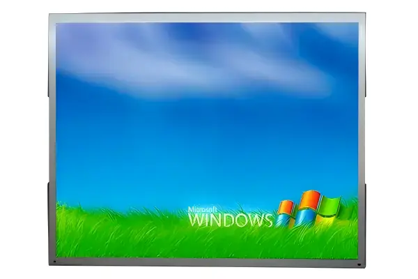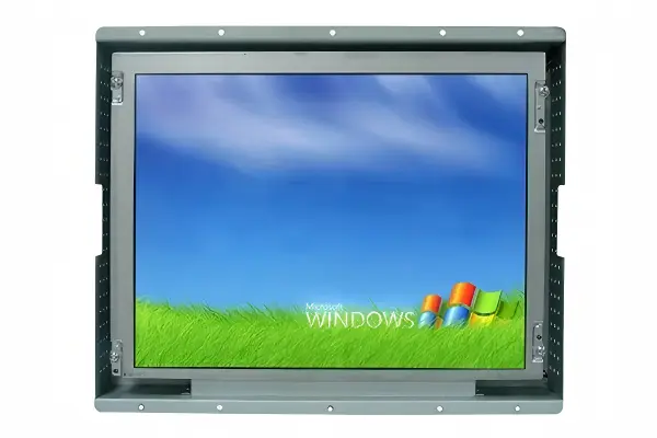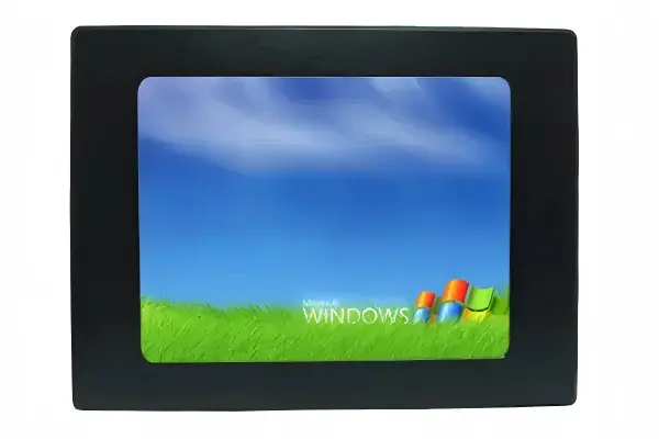
An industrial monitor datasheet can look simple until a replacement or new integration reaches the installation stage. Buyers often compare screen size, resolution, and price first, then discover a missed mounting, clearance, or cable-access detail. I recommend reading the datasheet as an installation risk check, not a basic parameter list.
An industrial monitor datasheet should be read from the mechanical drawing outward: confirm the monitor fits the enclosure, mounts securely, connects without cable obstruction, and remains serviceable after installation. Screen size, resolution, and interface matter, but they do not prove that two monitors are physically interchangeable.
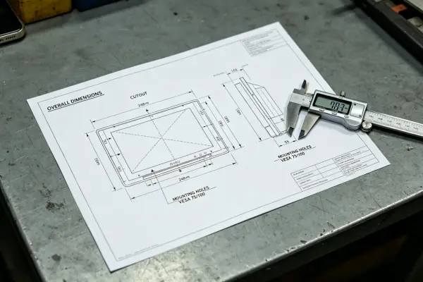
I have supported many specification-review conversations where an R&D or procurement team began with a familiar question: “Is this the same size screen?” The more useful question is usually: “Can this monitor be installed and maintained in our equipment without redesign?”
Why Should I Read the Industrial Monitor Datasheet Mechanical Drawing First?
A monitor may match the required diagonal size and resolution but still create an integration problem. This can lead to revised drawings, delayed sampling, or another replacement search. I suggest that buyers start with the mechanical drawing because it reveals whether the product can physically work in the target equipment.
The mechanical section of an industrial monitor datasheet should be reviewed before headline display specifications. Buyers should compare overall dimensions, front cutout requirements, bezel geometry, mounting points, rear depth, connector positions, and cable-exit space against the actual enclosure drawing, and can cross-check the wider criteria in our industrial LCD monitor selection guide.
Screen Size Does Not Define the Outer Dimensions
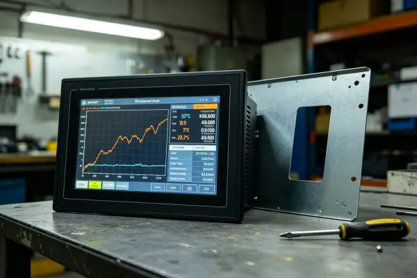
A 15.6-inch display describes the diagonal active viewing area, not the complete monitor enclosure.[1] Two 15.6-inch industrial monitors can have different:
- Bezel widths
- Overall width and height
- Enclosure depth
- Front-panel profile
- Mounting-hole locations
- Touch-overlay thickness
- Connector layouts
For example, a monitor may fit through an existing front opening but have a wider rear housing than the previous model. Another unit may have the same outside dimensions but a different VESA pattern or panel-mount stud position.
Read the Drawing in a Practical Order
I recommend reviewing these items in sequence:
- Overall dimensions: Confirm width, height, and depth.
- Front cutout size: Check the required enclosure opening for panel-mount models.
- Bezel and active area: Confirm the visible image area aligns with the equipment fascia.
- Mounting method: Identify VESA holes, side brackets, rear studs, rack ears, or panel clamps.
- Rear clearance: Allow space for the housing, connectors, cable bend radius, and ventilation.
- Service access: Confirm technicians can reach cables, fasteners, USB ports, or control buttons after installation.
In one anonymized specification discussion, I saw a team compare two monitors based on a matching resolution and front-facing size. When we reviewed the drawing together, the rear connector orientation became the deciding factor. The monitor itself could fit, but the cable route could not fit within the available enclosure depth.
Which Industrial Monitor Datasheet Dimensions Affect Installation Most?
Mechanical compatibility is rarely decided by one dimension. A monitor can pass the front-opening check and still fail because the rear enclosure, cable path, or mounting hardware conflicts with nearby components. I encourage teams to assess the complete installation envelope rather than only the visible front face.
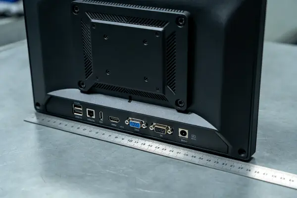
The most important industrial monitor datasheet dimensions are the total enclosure size, panel cutout, bezel overlap, mounting-hole pattern, monitor depth, connector location, and required cable-bend space. These dimensions determine whether the display can be installed securely and serviced inside the equipment.
Key Dimensions to Compare
| Datasheet Item | What It Tells You | Common Integration Risk |
|---|---|---|
| Overall W × H × D | Full monitor envelope | Housing contacts internal components |
| Cutout dimension | Required front opening | Display cannot enter or seal correctly |
| Bezel size | Front overlap around opening | Visible gaps or interference with controls |
| VESA or mounting holes | Fastener positions | Existing bracket cannot be reused |
| Rear depth | Space behind the front panel | Insufficient internal clearance |
| Connector position | Cable direction and access | Plug hits enclosure wall |
| Net weight | Load on bracket or door | Weak mounting structure |
| IP-rated front area | Environmental protection boundary | Incorrect gasket or installation method |
Do Not Ignore Cable Bend Space
Connector space is often underestimated. HDMI, DisplayPort, USB, VGA, and DC power plugs extend beyond the monitor housing. Their cables also need room to bend without excessive stress.[2]
I generally ask buyers to check:
- Does the connector point downward, sideways, or straight backward?
- How much distance exists from the port to the enclosure wall?
- Does the cable manufacturer specify a minimum bend radius?
- Can a technician disconnect the cable without removing other components?
- Will the cable path interfere with fans, power supplies, doors, or moving mechanisms?
A right-angle connector may help in a shallow enclosure, but it should be evaluated as part of the buyer’s system design. I do not treat a datasheet review as final system-level engineering approval. The equipment manufacturer should complete its own mechanical validation with drawings, samples, and qualified engineering review.
Mounting Method Must Match the Equipment
Industrial monitors may use panel mounting, open-frame mounting, VESA mounting, rack mounting, or custom brackets, and these methods are not automatically interchangeable.[3]
For a panel-mount monitor, buyers should verify the cutout, bezel overlap, mounting clamps, stud locations, and gasket contact surface. For an open-frame monitor, buyers should confirm where brackets attach and whether the equipment provides sufficient support points. Cutout, gasket, and clamp details are covered in more depth in our panel-mount monitor buying guide. For VESA mounting, the hole pattern alone is not enough; bracket strength, screw engagement, and load direction also matter.
How Do I Use an Industrial Monitor Datasheet for Replacement Selection?
Replacement projects often begin under time pressure. A discontinued display, damaged unit, or upgrade requirement can make a similar-looking monitor appear suitable. That approach creates risk when the replacement differs in depth, mounting, power input, touch interface, or connector access.
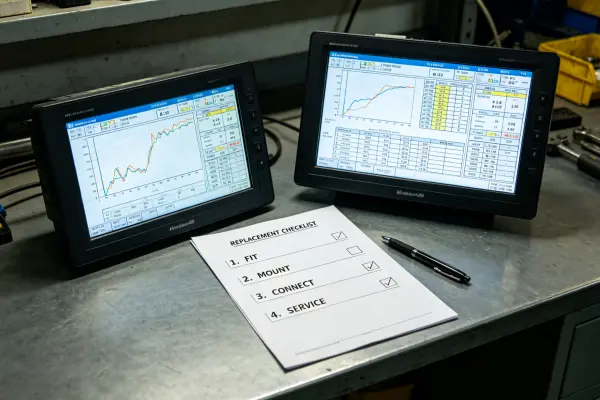
To use an industrial monitor datasheet for replacement selection, buyers should verify four conditions: the replacement fits the enclosure, mounts securely, connects without obstruction, and can be serviced after installation. A matching screen size or resolution should be treated as only an initial filter. These checks fit into the wider process described in our industrial LCD monitor selection guide.
A Four-Part Replacement Checklist
I recommend that OEM teams convert “Can I replace this monitor?” into the following documented checks.
1. Can It Fit?
Compare the old and proposed monitor drawings side by side:
- Overall width, height, and depth
- Front cutout and bezel overlap
- Active display area
- Touch glass thickness, if applicable
- Rear protrusions and connector zones
2. Can It Mount Securely?
Confirm that the existing mechanical structure supports the proposed unit.
A front opening is not a mounting system. The monitor needs defined fastening points and sufficient structural support.
Review the mounting-hole pattern, thread type, screw depth, clamp arrangement, and allowable load. If the prior monitor used custom side brackets, ask for the bracket drawing rather than assuming a VESA-compatible replacement.
3. Can It Connect Without Obstruction?
Verify video input, touch interface, power input, grounding needs, and cable routing. A monitor may offer HDMI and USB touch, for example, but the equipment may require a locking connector, 24 VDC input, or a cable route that the new connector layout cannot support.
4. Can It Remain Serviceable?
Serviceability affects the total ownership experience. I advise teams to consider whether a technician can remove the monitor, reach its connectors, replace a cable, and access control buttons without dismantling major equipment assemblies.
At AplusLCD, I would normally request the equipment opening size, available rear depth, mounting drawing, preferred interface, voltage requirement, and application environment before recommending a configuration. Our review can help identify visible specification mismatches, but the buyer should still perform final fit and system validation for the intended application.
Frequently Asked Questions
Can I replace an industrial monitor with the same screen size?
Not necessarily. The same diagonal size does not confirm matching enclosure dimensions, cutout size, bezel shape, depth, mounting holes, connector positions, or power requirements. I recommend comparing the complete mechanical drawings before selecting a replacement.
What is the most important part of an industrial monitor datasheet?
For installation planning, I consider the mechanical drawing the most important starting point. It shows the physical dimensions, mounting points, cutout requirements, depth, and connector placement that determine practical compatibility with the equipment enclosure.
How much rear clearance does an industrial monitor need?
The required clearance depends on monitor depth, connector orientation, cable bend radius, ventilation needs, and service access. Buyers should not use a generic clearance value — they should verify the proposed monitor drawing and the selected cable specifications.
Does VESA mounting guarantee compatibility?
No. VESA compatibility only confirms a hole pattern when the pattern and mounting dimensions match. Buyers should also verify screw size, thread depth, bracket strength, monitor weight, installation orientation, and access to ports after mounting.
Should I request a sample before a production order?
For a new integration or replacement project, I recommend a sample-based validation process whenever practical. A sample allows the buyer’s engineering team to check physical fit, cable routing, image performance, touch behavior, and system interaction in the actual equipment.
Conclusion
Reading an industrial monitor datasheet correctly means looking beyond screen size, resolution, and price. I recommend that OEM and procurement teams begin with the mechanical drawing, then confirm fit, mounting security, cable access, and serviceability. This process helps identify installation questions earlier, before a monitor reaches the equipment assembly stage. If you are evaluating an industrial monitor replacement or custom configuration, contact AplusLCD with your enclosure drawing and operating requirements for a specification review.
Footnotes
-
"Display size", https://en.wikipedia.org/wiki/Display_size. Display size is conventionally specified by the diagonal dimension of the visible display area; it does not by itself specify the monitor enclosure's width, height, or depth. Evidence role: definition; source type: encyclopedia. Supports: Display size is conventionally expressed as a diagonal measurement of the visible display area, which is distinct from the device's external dimensions. ↩
-
"Fiber Optic Cable Bend Radius or Diameter", https://www.thefoa.org/tech/ref/install/bend_radius.html. Cable-installation guidance specifies minimum bend radii because bending a cable too tightly can impose damaging mechanical stress and may impair cable performance or service life. Evidence role: mechanism; source type: association. Supports: Observing a cable's specified minimum bend radius helps prevent installation-related mechanical damage and performance degradation. Scope note: The applicable bend radius varies by cable construction, connector, temperature, and manufacturer specification. ↩
-
"VESA mount", https://en.wikipedia.org/wiki/VESA_mount. Display mounting is defined by the mechanical interface provided by the product; the VESA Flat Display Mounting Interface is one standardized example, while panel, rack, and custom installations use application-specific arrangements, and a standardized interface does not make those methods automatically equivalent. The VESA interface defines dimensional mounting patterns, so compatibility depends on the applicable pattern and its associated mounting specifications matching. Evidence role: definition; source type: institution. Supports: Display products use distinct mechanical mounting interfaces, and VESA compatibility is based on defined mounting-interface dimensions and related requirements rather than the general fact that a display can be mounted. Scope note: Matching the VESA pattern alone does not verify mount load capacity, installation orientation, screw engagement, or clearance for ports; a mounting-interface reference also does not establish that every industrial monitor is available in each listed form factor. The exact compatibility determination still requires the monitor drawing, mount documentation, and installation conditions. ↩